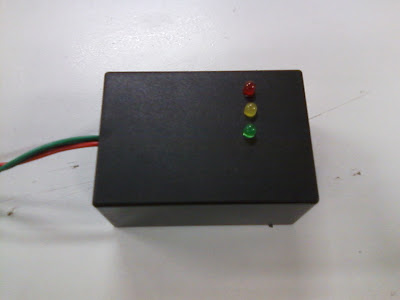
O2 Sensor Tester
The first thing I did in this unit was make a Lambda Sensor Tester (or 02 sensor).
This is used to Identify the signal of the O2 sensor of a EFI engine, that it is sending to the ECU of the car. This allows the driver to see the air fuel mixture while driving. As the O2 sensor detects Ratio it lets of a Voltage that is different depending on whether the engine is running a rich, lean or Stoich mixture.
- If running rich Red LED will glow (above 0.63V) this LED should be only on when Car is accelerating or when engine is cold.
- If Stoich (Ratio of 14.7:1) Yellow LED will glow (0.23V - 0.63V) this LED should only be on intermittently and not stay on all the time.
- If running lean Green LED will glow ( below 0.23V) this LED should only be on when decelerating while engine is warm. or when engine has just been turned on after a period of not running. (eg. when car has been sitting overnight.)
To make this required a PCB board to be assembled using:
- 7 Resistors of different values,
- 4 diodes,
- 3 LEDs,
- 2 capacitors,
- 1 Microchip and 3 wires.
 |
| LEDs Soldered into Board |
 |
| All components Soldered into board on opposite side to LEDs |
 |
| Box used to house board. 3 holes were drilled into cover of box to allow LEDs to be visible and 1 hole in side of box to allow wires to exit box |

No comments:
Post a Comment